Monday, 1 June 2020

Mikroe Buck 5 Click with PSoC5 VDAC

Summary
This post examines alternate means for driving the MikroElektronica Buck 5 Click hardware. First, the onboard digital Potentiometer was rewired in a new configuration and second the Potentiometer was replaced with Cypress PSoC.

Buck 5 Click - Courtesy MikroElektronica

Buck 5 Click with Digital Potentiometer and PSoC5
MikroElektronica's Buck 5 Click (MIKROE-3100) hardware presented itself as a cost-effective and off the shelf unit for testing the MAX17506 DC-DC Converter. The Buck 5 Click was designed primarily for use with other MikroElektronica hardware. The input voltage range of the Maxim buck converter (4.5V to 60 V DC) is not fully utilised on the Buck 5 Click (5V to 30 V DC). In the same manner, the output voltage appears capped at 20 V DC maximum. Even with the voltage limits the output range of the hardware was able to be tweaked. 


Wiring a Cypress CY8CKIT-059 prototyping kit to drive the Buck 5 Click required three connections for the SPI and two for power. The Buck 5 Click schematics indicated the board logic operated with 3.3 V DC however, the board was powered from 5 V DC. The supply range of the MAX5401 digital Potentiometer (pot) was 2.7 V to 5.5 V DC.

To control the digital pot, a PSoC Creator application using an SPI Master component was created


SPIM_WriteTxData(Buck5_Dig_Pot_Val);
while (0u == (SPIM_ReadTxStatus() & SPIM_STS_SPI_DONE)) 
{ }


The subsequent step of increasing the output voltage range of the Buck 5 Click was accomplished although the configuration of feedback resistor network (R8) and digital pot (U2) for the DC-DC converter (MAX17506) needed to switch places. The digital pot operating voltage was the reason for the change. The pot wiper was connected directly into the feedback pin of the MAX17506. Below is a working board with modifications.


Buck 5 Click Modified with Increased Output Range


The output voltage range of the modified board was approximately 4V to 18 V DC. The digital pot, with 255 positions, provided output voltage steps of 55 mV.

When applying power to the digital pot, the default setting is the middle position which may not be ideal in all instances. To control the behaviour of the buck regulator on power-up, a connection from the PSoC to the Enable line of the Buck 5 Click was used. A pull-up resistor (R4) was removed from the board to prevent the Buck 5 Click from starting when power was applied

Buck 5 Click with Cypress PSOC5 VADC, No Digital Potentiometer
Other solutions for adjusting the output voltage of a DC-DC converter, through control of the feedback pin, use external PWM or DAC sources.

The Cypress PSoC provides control of DC-DC converters either through PWM (Trim and Margin component) or a DAC (Current or Voltage component). This post used the PSoC VDAC8 component which provided 255 steps. For additional resolution the dithered VDAC component with 4096 steps could be used.

For calculating the output voltage for VDAC solution, Maxim published a notable tutorial deriving the output equation shown below from first principles.

VOUT = VREF(1 + (R1/R2)) + (VREF - VDAC) (R1/R3)                        Eq (1)

For connection of the VDAC to the feedback loop of the DC-DC Converter, one additional resistor (R3) was required.


DC-DC Converter Output Voltage Control Using a DAC

A spreadsheet was used to implement Equation (1) which allowed the three unknown resistor values to be manually changed and the output voltage range of the DC-DC converter observed.

DC-DC Converter Vout Spreadsheet Calculations

Equation (2) was used to ensure that the maximum current seen by the PSoC (DAC) was less than 25 mA.

i3 = (VREF - VDAC)/R3                       Eq. (2)

Quadrature Encoder
A quadrature encoder (Bourns PEC11R) was added to the design to allow for manual voltage adjustments. The QuadDec component was used to convert the encoder AB lines. The QuadDec returned value was limited to between 0 and 255. The reading from the QuadDec was then used to adjust the output of the VDAC component.


PSoC Creator Top Design
The project required the QuadDec, DAC and OpAmp components as shown below.


PSoC Creator Project Top Design


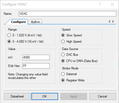
The calculations in Excel used a voltage range from 0.1 V to 4.08 V which was the option selected in the VDAC component.

VDAC Component Settings

While not essential, an OpAmp follower was added to the design.

OpAmp Component Settings

To maintain 255 positions the QuadDec component was changed from the default 8 bit to 16 bits.

QuadDec Component Settings

The remaining signals that are shown on the PSoC Creator project page (Top Design) were related to the DC-DC converter (PSU_Enable) and the on-board switch (Switch1). Voltage ramps were generated in code on start-up then Switch1 was pressed.

To facilitate testing of the encoder, a UART component was added to the project.

PSoC Creator Pin Mapping
Pin mapping for the design is shown below.


PSoC Project Pin Mapping


PSoC Creator Code
Listed below is an extract of some quick and grubby code used for testing the Mikroe with the PSoC Creator prototyping board.


/**
* @brief Main init and update VDAC based on quadrature encoder value
*/
int main()
{
  uint16_6 Encoder_Count, Encoder_Count_last = 0;
CyGlobalIntEnable();
QuadDec_Start();
UART_Start();
Opamp_Start();
VDAC_Start();
CyDelay(2000); /* Time to stabalise */
PSU_Enable_Write(true); /* Switch DC DC On */
pulse_on_switch1();
for(;;)
{
Encoder_Count = QuadDec_GetCounter();
if (Encoder_Count != Encoder_Count_Last)
{
if ((Encoder_Count <= MAX_ENC) && (Encoder_Count >= MIN_ENC))
{
write_to_uart(Encoder_Count);
VDAC_SetValue(Encoder_Count);
}
else if (Encoder_Count > MAX_ENC)
{
Encoder_Count = MAX_ENC;
QuadDec_SetCounter(MAX_ENC);
}
else if (Encoder_Count < MIN_ENC)
{
Encoder_Count = MIN_ENC;
QuadDec_SetCounter(MIN_ENC);
}
Encoder_Count_Last = Encoder_Count;
}
}
}

The functionality of the test code was to read the Quadrature Decoder, ensures the value read was within the range, then write the value to the VDAC.


Hardware Setup
Shown in the image below is the hardware setup which consisted of the Buck 5 Click, PSoC board and the rotary encoder.


Buck 5 Click with Increased Output and PSoC VDAC

Output Voltage Range and Regulation
The calculated output voltage range was for 1.62 V to 20.33 V DC and the measured range was 2.39 V to 20.42 V DC.

Rudimentary load tests were conducted with a resistive load driven by the Buck 5 Click. Tests indicated a 0.25 % voltage regulation with low loads (1W) and better than 0.1 % with higher loads (65 W). The DC-DC converter used in the Buck 5 Click (MAX17506) has a capability of 5 A. The full load current was not load tested.

Output Voltage Adjustment using PSoC
To change the output voltage of the DC-DC converter without the encoder, the value written to the VDAC was controlled in software. When the switch located on the Cypress CY8CKIT-059 prototyping kit was pressed on power-up, the code generated several pulse types.

Buck 5 Click Output Voltage Waveform from PSoC VDAC
Buck 5 Click Output Voltage Waveform driven from PSoC VDAC

The capture above shows the Buck 5 Click output voltage ramp up and down with a 220 R resistive load.

Final Thoughts
The MikroElektronica Buck 5 Click was a reliable hardware module which allowed a Cypress PSoC to be interfaced for testing. Using a DAC to adjust the output voltage provided an alternative method to the on-board Potentiometer. The option to use PWM control for voltage adjustment was not reviewed in this post although this method should be considered as another solution.


Downloads
PSoC Creator 4.3 Power Supply Project (PSU) Project.

PSoC Creator 4.3 PSU Project

Saturday, 2 May 2020

PSOC Unused I/O Pins

Summary
This blog reviews GPIO configurations for unused PSoC microcontroller pins with a focus on the resulting differences in current usage.

Cypress PSoC4 Controller

Existing Literature
Information relating to the handling of unused pins can be located for most microcontrollers, for example AVR or Microchip. Companies such as Analogue Devices have posted similar unused pin information in their monthly Analog Dialogue.

Between the Cypress Technical Reference Manuals (TRM) and the Cypress community forummethods for handling unused processor pins have been detailed or discussed in numerous times.  Forum suggestions for managing unused pins varies from configuring the pins as high impedance digital inputs, to resistive pull-up/pull-down to outputs.

The PSoC4 TRM states on page 64 under the High Impedance Analogue heading that unused GPIO pins should be configured as high impedance analogue pins (PSoC 4100/4200 Family PSoC 4 Architecture TRM, Document Number: 001-85634 Rev. *H).

While the TRM does not detail the benefits of terminating unused pins with pull-up / pull-down resistors or the effects of EMC / EMI on floating pins, one of the salient remarks in the extract from the TRM is 'unused GPIOs must be configured to the high-impedance analog'. The previous comment relates primarily to current consumption in low-power modes, however the pin configuration could be inferred for unused pins.

High-Impedance Analog
High-impedance analog mode is the default reset state; both output driver and digital input buffer are turned off. This state prevents an external voltage from causing a current to flow into the digital input buffer. This drive mode is recommended for pins that are floating or that support an analog voltage. High-impedance analog pins cannot be used for digital inputs. Read-ing the pin state register returns a 0x00 regardless of the data register value. To achieve the lowest device current in low-power modes, unused GPIOs must be configured to the high-impedance analog mode.

For pins configured as high impedance (digital), Electronic Design is one of the sites which details the reason why high impedance digital inputs are not preferred. An extract from the Electronic Design site is detailed below.

Over time, however, the floating input tends to accumulate a charge and float toward the logic level change-over point. When it reaches that point, it causes both the high and low MOSFETs to be partially on, resulting in shoot through current.

To provide a visual representation of shoot through current mentioned in the above extract, consider a post such as this from the Texas Instrument forum.


Shoot Through Current - Courtesy Texas Instruments

Certainly other technical sources indicate that pin configurations should be resistively biased or configured as outputs only. Time to perform a few measurements to verify the pin configurations!

PSoC Current Measurements 
To perform current measurements of the PSoC4 on the bench, a surplus PCB from a previous project was loaded with minimal components. A PSoC4, a pull-up resistor for the reset line and some essential capacitors were fitted to the board.


Cypress Microcontroller with Unused Pins

PSoC Programming was performed using a Miniprog.

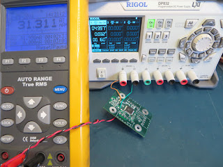
The supply (5 VDC) was provided from a bench supply, Rigol DP832, as shown in the image below. Current measurement was made using a standard digital multimeter.

PSoC4 Bench Setup for Current Measurement

The PSoC Creator application used the pin component to configured the entire port. Any change made to the pin type was reflected for all pins on the port.

PSoC Creator Top Design All Pin Configuration

Two current measurements were taken as verification. The power supply current measurement was verified against the multimeter.

Measurement Results
Measurements were performed on a PSoC4 (CY8C4245AXI-483) with GPIO drive modes (type) 0 - 4 and 6 - 7.


PSoC4 GPIO Drives Modes
PSoC4 GPIO Drives Modes - Courtesy Cypress Semiconductor

For the GPIO types listed in the table below, the default PSoC Creator settings were used. All pins were configured for contiguous mapping except for high impedance analogue inputs which required the contiguous mapping to be disabled.

PSoC4 Overall Current Measurement for GPIO  Configurations
PSoC4 Overall Current Measurement for GPIO  Configurations

The High Impedance Digital Input GPIO type had a striking difference in measured current compared to the other types.

Final Thoughts 
High Impedance Digital Inputs resulted in the highest overall current consumption of an active PSoC4 device. From the brief range of measurements performed in this post it would be prudent not to configure unused PSoC pins as High Impedance Digital.

Unused PSoC pins should be configured with internal resistor biasing or as outputs where practicable.

PSoC Project
For readers interested in verifying or disprove this post, the PSoC Creator project is made available.


PSoC Creator Project - Test PSoC

Sunday, 5 April 2020

Rexon RDM150D Retrofit ESTOP Stage 2

Summary
This blog details the second stage retrofit of a Rexon RDM150D drill press. The second stage added movement monitoring of the spindle and a requirement to  deactivate the drill press run switch after triggering the ESTOP. The first stage retrofit blog contained details relating to controller design and the drill press wiring.

Electrical Wiring - Stage 1
The first stage changes to the drill press electrical, which included the ESTOP button and controller, are shown in the image below.


Rexon RDM150D Stage 1 Electrical

Electrical Wiring - Stage 2
For the second stage retrofit, a proximity switch and a relay were added to the design. Both the new devices were connected to the controller.


Rexon RDM150D Stage 2 Electrical
Inductive Sensor
For detection of rotational movement in the pulley responsible for driving the spindle, an inductive sensor was selected.

MCPIP-T12L-001 Courtesy Multicomp
      MCPIP-T12L-001 Courtesy Multicomp

The sensor was manufactured by Multicomp, part MCPIP-T12L-001, which features a PNP output, M12 thread and a 2mm sensing distance.


Inductive Sensor PNP Electrical Connections
DIN Relay
A relay was added to detect when the manual switch (DPDT) was in the ON state. Providing the manual switch state to the controller served two purposes, firstly the controller could determine when the spindle was active and secondly the same feedback signal could be used to ensure that the manual switch was OFF before the contactor was reactivated.


DIN Relay 2909526 Courtesy Phoenix Contact

The relay used was a DIN style, 240V input, from Phoenix Contact.

As shown in the second stage electrical drawing above, the input to the relay was driven from the equipment side of the manual ON OFF switch. The pair of secondary side relay Normally Open connections were individually connected to 24V and the Spindle Active input of the controller.


Sensor Hardware and Mounting
An oversight with the Multicomp sensor installation was the devices body length which prevented the sensor being mounted between two pulleys.


Sensor Mounting Bracket
To mount the sensor inside the top housing of the drill press, a repurposed wall bracket was drilled to the required hole size (M12). Loctite 243 was used on the sensor thread. The bracket was fitted at an angle as shown in the above image. This prevented use of the lowest belt position between the spindle and middle pulleys. A shorter sensor, placed parallel to the belts, would be recommended for those implementing this design.

Triggering the sensor was achieved using a small steel angle fitted to the pulley. For a speed of 3000 RPM, best results were achieved when the length of the steel angle was 20 mm. Two M3 bolts with Loctite 243 and internal star washers were used to fix the steel bracket in position.


Sensor Steel Pulley Bracket

Sensor Test Measurement
With the Multicomp sensor powered and an Oscilloscope fitted to the Out connection, one measurement was taken at a slow RPM and the second measurement at the fastest RPM.

Slow RPM Sensor Measurement

Fast RPM Sensor Measurement

Relay Mounting
The DIN relay was mounted between the contactor and the controller, as pictured below.

Electrical Enclosure DIN Relay Mounting

PSoC Inputs
The spindle and spindle active inputs to the PSoC controller were provisioned in the first stage controller design. Connections were made according to the updated inputs detailed in the section below.

PSoC Inductive Spindle Input

Controller Wiring
A correction was required to the controller PCB overlay. The capture below shows the updated overlay reflecting the controller connections.

Retrofit Rexon Controller Updated PCB Overlay

Controller Option
To identify new features were added to the controller, one of the option resistors was populated on the controller PCB.


Enabling Controller Option on PCB

PSoC Code Changes
The principal change to the PSoC was the addition of logic for counting pulses from the inductive sensor.


PSoC Windowed Pulse Counter

A timer solution was implemented fifty percent duty cycle with a period of 499 ms. During the On time the Timer_Spindle component accumulated counts from the Spindle input. At the end of the capture the isr_Spindle fires allowing the count value to be retrieved. For the remainder of the period no counting was performed. The Sync component was used to synchronise the slower PWM_Spindle clock with the Timer_Spindle clock.

Monitoring of the spindle active input and spindle speed was moved into a basic state machine, extract listed below.


/**
* @brief Basic State Machine for handling ESTOP and Spindle signals
*/

void State_Mach_Mon(void) 
{
    switch (Spindle_Monitor_State)
    {
    case (state_m_idle):
        if (Status_ESTOP_Read() == 1u)
        {
            Spindle_Monitor_State = state_m_es_deact;
        }
    break;

   case (state_m_es_deact):
        Control_ESTOP_Write(0x1); 
        if (Status_ESTOP_Read() == 0u)
        {
            Spindle_Monitor_State = state_m_reset;
        }

        if (Spindle_Active_Read() == true)
        {
            PWM_Spindle_Start();
            Timer_Spindle_Start();
            Spindle_Monitor_State = state_m_es_sp_act;
            Spindle_Started = true;
            Spindle_Timer = 100u; 
        }
    break;

    case (state_m_es_sp_act):
        Spindle_Count_Update();
        if (Status_ESTOP_Read() == 0u)
        {
            Spindle_Monitor_State = state_m_es_reset;
        }

        if (Spindle_Active_Read() == false)
        {
            Spindle_Monitor_State = state_m_reset;
        }

        if ((Spindle_Counts == 0) && (Spindle_Timer == 0))
        {
           Spindle_Monitor_State = state_m_es_reset;
        }
    break;

    case (state_m_es_reset):
        PWM_Spindle_Stop();
        Timer_Spindle_Stop();
        Control_ESTOP_Write(0x0); 
        Spindle_Started = false;
        if (Spindle_Active_Read() == false)
        {
            Spindle_Monitor_State = state_m_idle;
        }
    break;       

    case (state_m_reset):
        Control_ESTOP_Write(0x0);
        PWM_Spindle_Stop();
        Timer_Spindle_Stop();
        Spindle_Monitor_State = state_m_idle; 
    break;
    } 
}

Additional changes were made in the code to read pulses measured by the spindle sensor counter and also to determine the configuration of the PCB version (function) resistors.

Option Resistors
Notes for the code option resistors was into the PSoC project.


PSoC Notes for Option Resistors

In the PSoC code, the various resistor combinations were used to define the controller operation.

/**
* @brief Board Options
*/
void Board_Options(void)
{
    if ((Option0_Read() == false) && (Option1_Read() == false))
    {
        System_Flags.Option_None = true;
        UART_UartPutString("No option\r\n");
    }
    else if ((Option0_Read() == true) && (Option1_Read() == false))
    {
        System_Flags.Option_Spd_Mon = true;
        UART_UartPutString("Speed monitor option\r\n"); 
    }
    else if (((Option0_Read() == true) && (Option1_Read() == true)) || ((Option0_Read() == false) && (Option1_Read() == true)))
    {
        UART_UartPutString("Unknown option\r\n"); 
    }
}

Sensor Counts
As the pulse counter configuration provided a 250 ms sampling window, the multiplier for the number of counts was set to 240.

/**
* @brief Read Spindle Counts and Report
*/
void Spindle_Count_Update(void) 
{
    if ((Spindle_Data_Ready == true) && (Spindle_Started == true))
    { 
        Spindle_Counts = Spindle_Raw*240u;
        Spindle_Data_Ready = false;
        ReportData();
    }
    Flag_Timer = false;
}

The Report Data function was used to provide the spindle speed in RPM. Data was output on a UART as shown in the capture below from TeraTerm.


Controller Spindle Speed Output in TeraTerm

A timer, defined by variable Spindle_Timer, ensured that when the spindle was not spinning for one second, the drill press motor would be switched off using the contactor.

Final Thoughts
The controller in this blog could be adapted for other workshop machinery, which was not originally manufactured with a method to stop that machinery in a controlled manner. Features such as the spindle rotation monitoring could be removed or disabled and other features added to suit the machine setup.

Downloads


ESTOP v1.1 BOM XLS
ESTOP v1.1 BOM XLS
ESTOP v1.1 Schematics PDF
ESTOP v1.1 PCB PDF
ESTOP v1.1 PCB PDF
ESTOP v1.1 Gerbers
ESTOP v1.1 Gerbers
ESTOP  v1.1 PSoC Doxygen
ESTOP v1.1 PSoC 4.3 Project
ESTOP Module PSoC Creator Top Design PDF