Thursday, 11 April 2019

Diode charging supercap solar battery

Summary
This post investigates the ideal diode my Maxim Integrated, part MAX40203, as a possible replacement for low forward voltage diodes.


Example Diode SuperCapacitor Charger
Forward Voltage
When deciding on a suitable diode for a circuit, such as the basic diode supercapacitor charger shown above, a Schottky is a usual choice. The lower forward voltage of the Schottky diode is more beneficial to ensure that the load operating voltage is closer to the supply voltage. There is also the benefit of lower losses as a result of the lower forward voltage.

Some examples of different Schottky diodes include the Toshiba CUS10S30 with a voltage drop of 230mV at 100mA, the Panasonic DB2S30800L has a drop of 420mV at 100mA or the Nexperia PMEG10020 with a drop of 500mV at 100mA.

Ideal Diode
Released in the middle of 2018 the MAX40203 is targeted as a replacement for the Schottky diode and it does not disappoint in regards to forward voltage.


MAX40203
MAX40203 - Courtesy Maxim Integrated
Diode Testing (Reverse leakage)
To begin the tests, reverse leakage was measured. The MAX40203 was bench tested against two general Schottky diodes, the Nexperia PMEG10020 and an ST STPS2L40U. To perform tests with the Schottky diodes, the devices were connected in reverse bias with a 100k resistor. The MAX40203 leakage test was performed with 100k resistors to measure leakage through Anode and GND as shown in the device datasheet.


MAX40203 Leakage - Courtesy Maxim Integrated
Voltage measurements were made across the resistor as the supply voltage was increased in one volt increments. Since the maximum operating voltage of the Maxim part is 5.5VDC the test voltage was limited to 5V.

Reverse leakage Schottky vs MAX40203
Graphing the above table of results was certainly not necessary although illustrates the leakage difference between devices. Note the reverse leakage on the PMEG diode is magnitudes lower than the Maxim part. At 5V DC the PMEG diode leakage was 30nA compared to the 207nA for the Maxim part.


Graphed reverse leakage Schottky vs MAX40203
Maxim Part Enable
The MAX40203 datasheet does state that the Enable pin should be pulled high however it also states that there is an internal weak pullup.

Reverse leakage tests were performed with only the Maxim device and the leakage through the Anode was measured. Once again the power supply voltage was increase in a range of 1C to 5V DC.


MAX40203 Reverse Leakage Test Setup
These tests were to replicate a circuit, such as the example above, using a solar panel.


MAX40203 Enable On/Off Reverse Leakage Measurements
Some difference in measurements was noted when the Enable input was connected to the supply. 

Diode Testing (Forward Voltage)
The MAX40203 was subsequently tested with the diodes from the previous test in forward bias. Resistive loads were changed with a fixed supply voltage of 5V DC to achieve test currents from 1mA to 1A.


Forward Voltage Schottky vs MAX40203
Graphing the above data illustrates the usual curves for diode forward voltage with the almost linear voltage drop against forward current across the MAX40203 internal FET.


Graphed forward voltage Schottky vs MAX40203
MAX40203 Load Testing
Measurements were taken to verify the forward voltage of the Maxim part against the device datasheet to a current of 1A. These were similar to the specifications for a room temperature of 25°C and not recorded.

For the final set of tests the MAX40203 was powered up and down with varying resistive loads with a fixed supply voltage of 5V DC. A repurposed board served as the carrier for the test device.


MAX40203 Test Setup
MAX40203 Test Setup
Tests were performed with various wirewound resistors and initially the power supply current limited to 1A. Final tests were conducted with a current limit at 2A.
MAX40203 Load Test Results
The first three tests shown in the results above were relatively normal. For the last test with a 0.1Ω resistor the power supply current limit was increased to 2A. After power was supplied to the device, it warmed considerably then the current reduced to around 180mA so power to the device was removed. The internal protection was suspected to be active. After cooling the device did not output the supply voltage of 5V, instead it was around 4V DC. Furthermore the quiescent current was 32mA which had also increased.

MAX40203 Short Testing
A new MAX40203 was placed on a new test board as the device from the prior test was suspect. In the last test the output of the device was shorted to 0V to test the short circuit protection.

After applying power the supply showed that the device was passing and holding 1A. The current limit on the supply was then increased to 2A, still ok, then 3A; after 3A the current dropped to several hundred milliamps. The device was allowed to cool but never returned to normal operation.

Comments
Testing showed that the low forward voltage drop of the MAX40203 makes it ideal for specific charging applications. For a charging current of 100mA the test Schottky's 481mV was over ten times larger than the Maxim devices 35mV.

Conversely the reverse leakage of the Schottky 30nA was significantly lower than the 316nA for the Maxim device.

Testing of the Maxim device short circuit protection was incomplete and would warrant additional further review.


Friday, 8 March 2019

Altium Unable to cast COM object type

Summary
This blog describes how Altium users can resolve the "Unable to cast COM object type" which can be caused as a result of installing / uninstalling Office (32 bit) software together with Office (64 bit).

Altium Dialog Message
The "Unable to cast COM object type" message can be displayed when there is a requirement for Altium to use Excel libraries, such as generating a Bill of Materials (BOM).


Altium Dialog Message
The message identifies a registry entry which is located at HKCR\TypeLib.

Causes
One Microsoft blog explains that the message may be displayed within Office applications when a mixture of Office 32/64 bit applications are installed on the same machine. The Microsoft blog suggests removing the HKCR key 
00020813-0000-0000-C000-000000000046 although applying this change with Altium did not resolve the issue.


Registry 00020813-0000-0000-C000-000000000046 Entry
Registry 00020813-0000-0000-C000-000000000046 Entry
Office Repair
To remedy the issue in Altium, an Office Repair was required. With the Altium application closed, may not be necessary, the Apps and Features application was opened from the 'Start' menu and the relevant Office installation selected.


Windows 10 Apps and Features
The Modify button was selected followed by the Quick Repair.


Office Quick Repair
Office Quick Repair
Quick Repair Started
In a few minutes the repair finished.


Quick Repair Finished
After the repair Altium was launched and a BOM generated without any issues.

Other Altium Messages
While replicating the "Unable to cast COM object type" Altium message for this blog, the process of installing 32 bit Office software did interfere with another Microsoft redistributable. This resulted in Altium displaying a dialog detailing the missing redistributable. Fortunately the Altium dialog provided a link to the Microsoft website where an installation of the redistributable resolved the issue.

Saturday, 23 February 2019

Light Table using BenQ GL2430 Backlight

Summary
This blog illustrates how the salvaged LCD backlight from a BenQ model GL2430 monitor could be used in the design of a light table. 


GL2430-B  BenQ Monitor
GL2430-B BenQ Monitor
Just Another Light Table
Online suppliers such as Amazon have amazing light tables at prices which would force one to question why salvaged electronics should be used. In reply, this is a blog relates to salvaging, reusing electronic waste and my requirement was for dual purpose light table, home and workshop - this meant a robust and repairable solution.

LED Driver
In a previous blog relating to the salvaging of parts from a BenQ monitor, the LED driver and backlight were confirmed operational before starting the salvaging operation.

Further bench testing was needed to determine how the LED controller could be reused. At the core of the controller board sits a Monolithic Power System LED controller - MP3389. After perusing the datasheet a section on dimming on page 9 caught my interest.


MP3389 Typical Application
MP3389 Typical Application (Courtesy Monolithic Power Systems)

This section of the MP3389 datasheet describes dimming control using a PWM signal or a DC signal. Dimming was not an immediate requirement for this project, although it was advantageous to know if such a feature could be added if required.

MP3389 DC Dimming Control
Further on page 13 of the MP3389 datasheet is a figure displaying the DBRT (Brightness Control) input. In order to use dimming with an external DC input voltage, a capacitor must be connected to the BOSC (Dimming Repetition Set) pin.


MP3389 Dimming
MP3389 Dimming (Courtesy Monolithic Power Systems)
Checking the LED controller PCB it was apparent there was a resistor, R801, connected to the BOSC pin. This resistor was replaced with a small ceramic capacitor 0.033uF to set the required frequency.


MP3389 LED Controller Change R801 to Capacitor
The MP3389 datasheets lists the minimum operating voltage for the device as 5VDC. After the power connections were determine from the old BenQ loom, a benchtop power supply was set to 5VDC with a 500mA current limit.


BenQ Controller and Backlight
With the power supply limited to 500mA the intensity of the backlight was comfortable to look at in a room with fluorescent lights. Full current was close to 1.2A at 5V DC. With a variable resistor attached to the BRBT pin, the dimming voltage to the DRBT pin of the MP3389 was adjusted until the power supply indicated around 480mA.

Control PCB Mounting
By some odd chance the controller fit neatly into a plastic enclosure. This was a UB5 plastic enclosure from a local supplier.


Boxed MP3389 Controller
The variable resistor was measured between wiper and external terminals. This converted the variable resistor into two fixed resistors, 68k and 22k. As seen in the image below, the larger value resistor connected between the 5V supply and the dimming pin. The smaller value resistor connected between the dimming pin and supply 0V.


Boxed and Modified MP3389 Controller
A chassis mount DC jack was added to one side of the enclosure away from the PCB. Also a small slot was added for the loom and connector which attaches to the backlight assembly.

Frame Construction
An aluminium lipped tube was used for the construction of the frame. The lip was used to retain the backlight.


Lipped Aluminium Tube
To connect the frame together, plastic corner pieces were utilised.


Tube Corners
Tube Corners
The aluminium tube was cut into four pieces. Two at 555mm and the other at 325mm. A circular saw made light work of the tube.


Cut Aluminium Tube
Cut Aluminium Tube
Fitting the plastic tube corners was achieved with an engineer's square to check for square and a rubber mallet to massage the aluminium frame over the tube corners.


Aluminium Tube Corners Fitted
The remaining frame parts were assembled.


Aluminium Frame Assembled
A cut-out was required for the cable assembly which connected between the backlight controller and backlight. An area on the frame was marked out then removed with a Dremel.


Aluminium Frame Backlight Connector Markup
Aluminium Frame Backlight Connector Cutout
Control PCB
Two self-tapping screws were used to mount the control PCB enclosure to the aluminium frame.


Control PCB Enclosure Mounted to Aluminium Frame
For the connections to the control PCB, the original cable from the BenQ monitor was reused. The red, orange and green wires were connected to the 5V centre pin of the DC jack. These were the main supply and enable pins to the MP3389. The brown and black were connected to 0V of the DC jack. The white wire dimming connection was left floating and terminated in heatshrink.

To complete the control PCB assembly the cable to the backlight was plugged into the controller and the plastic lid attached.


Mounted Control PCB Enclosure
The exposed backlight cable was to be protected with flexible plastic trunking. 

USB Power Lead
The current limit set by the dimming resistors on the control PCB was less than 500mA. This value allowed off the shelf USB chargers or USB ports to power the light table.

A standard USB cable was modified so that only the USB power connected to the centre of the DC jack and the black to the outside of the jack.


USB Power Lead for Light Table
Acrylic Cover Sheet
A removable acrylic cover, 3mm thick, was cut out to cover the backlight. Having a removable cover sheet was necessary with the light table being used around home and in the workshop. 


Acrylic Cover for Light Table
Securing the Backlight
To secure the backlight into the frame, a bead of silicon was used between the four corners of the frame and the backlight body.


Fixing LED Backlight
Acrylic Mounting and Feet
Four self-tapping screws and Nylon washers were used to secure the acrylic sheet.
Securing the Acrylic Cover
On the rear side of the light table, four rubber feet were added to each corner.


Rubber Feet or Light Table
Backlight Diffuser
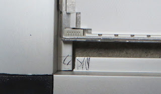
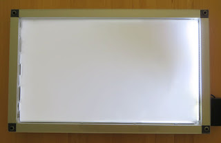
Using only the backlight diffuser which appears to be a type of translucent plastic film produces good uniformity. There were other optical sheets layered on the front of the original LCD although these were not used.


Light Table Test
Light Table Test
During cleaning of the acrylic with a dry cloth, the backlight diffuser became attracted to the acrylic and lifted off the backlight. An application of silicon helped reduce the lift of the backlight.


Saturday, 26 January 2019

Scripts with PSoC Creator (Powershell)

Summary
In a previous post, command line scripting was used to increment the build number for a PSoC Creator Project. The option to use command line 'cscript.exe' remains supported in Windows 10 although other scripting systems have made significant ingress into the corners of build scripts. This blog illustrates a quick alternative by using trusty PowerShell.

Why PowerShell
In companies where software deployment on desktop machines is not micromanaged, PowerShell can be a useful tools for scripting. Certainly Perl, Ruby, JavaScript or similar languages should not be excluded by IT support or software developers. PowerShell is offered for scripting with PSoC Creator as it is been available from Microsoft since 2006 and therefore available on the Windows operating system.

This blog will look only at Windows machines with PSoC Creator and not attempt to review the impact of scripts with virtual machines.

Example Scripts
The two scripts detailed in the sections below perform the action of copying a 'hex' file to a release directory in a parent folder. For the purposes of illustration the HelloWorld_Blinky program was used from the PSoC Creator examples.


PSoC Creator Hello World Blinky Example

Cscript

The example script below uses the File System Object with a few methods to copy the output file to another folder. If the release folder does not exist then it is first created. 

REM Release Directory Example for PSoC Creator

REM Setup file system access
Set fso = CreateObject("Scripting.FileSystemObject")

REM Setup operating parameters
ProjectMainFolder=fso.GetAbsolutePathName(".")
ReleaseMainFolder=fso.GetParentFolderName(ProjectMainFolder)
ReleasePath = ReleaseMainFolder & "\Release\"
SourceFile = ProjectMainFolder & "\DP8051_Keil_951\Release\*.hex"

Sub Create_Folder(intReleasePath)
 If fso.FolderExists(ReleasePath) Then
  WScript.Echo ("Folder exists...skipping")
 Else
  fso.CreateFolder(ReleasePath) 
  WScript.Echo ("Folder created")
 End If
End Sub

Sub Copy_File(intReleasePath)
 fso.CopyFile SourceFile,intReleasePath
End Sub

REM Duplicating required files
WScript.Echo ("Duplicating files at:" & ReleasePath &vbCrLf)
Create_Folder(ReleasePath)
Copy_File(ReleasePath)
WScript.Echo ("Completed")

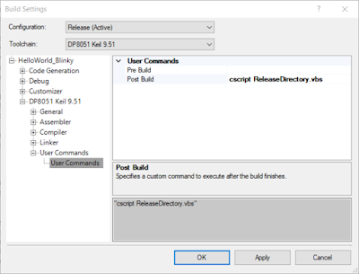
The script ReleaseDirectory.vbs is copied to the PSoC projects directory HelloWorld_Blinky.cydsn. A modification is made in the PSoC Creator project to the Build Settings under the Project menu. For this example the call, cscript ReleaseDirectory.vbs is placed in the post build section.


PSoC Creator Post Build Cscript
After the change above to the build settings the Hello World project is built resulting in the output below.


PSoC Creator Post Build Cscript in Output Window

The Output window shown above details the creation of the folder and completion of the file copy.

PowerShell
The example script below uses PowerShell commands to achieve the same functionality as the above Cscript. As this is for illustrative purposes only the operation of the two scripts may not be exact.

' Release Directory Example for PSoC Creator '

' Setup operating parameters '
$ProjectMainFolder=(Get-Item -Path ".\").FullName
$ReleaseMainFolder=(Get-Item -Path ".\").parent.FullName
$ReleasePath=$ReleaseMainFolder+’\Release\’
$SourceFile = $ProjectMainFolder+'\DP8051_Keil_951\Release\*.hex'

function Create_Folder($intReleasePath)
{
    if((Test-Path -Path $intReleasePath )){
        Write-Output "Folder exists...skipping";
    }

    if(!(Test-Path -Path $intReleasePath )){
        New-Item -ItemType directory -Path $intReleasePath
        Write-Output "Folder created";
    }
}


function Copy_File($intReleasePath)
{
 Copy-Item $SourceFile -Destination $intReleasePath
}

Write-Output "Duplicating files at:"
Write-Output $ReleasePath
Create_Folder($ReleasePath)
Copy_File($ReleasePath)

Similar to the previous example, the script ReleaseDirectory.ps1 is copied to the PSoC projects directory HelloWorld_Blinky.cydsn. In addition to calling the PowerShell script a parameter is passed to bypass the execution policy, PowerShell -executionpolicy bypass -File ReleaseDirectory.ps1

For this example the call is again placed in the post build section.


PSoC Creator Post Build Powershell

After the change above to the build settings the Hello World project is built resulting in the output below.

PSoC Creator Post Build PowerShell in Output Window
In the event that the policy to execute the PowerShell script was not allowed a security error message will be shown in the output window.

PSoC Creator Post Build PowerShell Error in Output Window
The execution policy can be checked using PowerShell ISE and amended with due consideration for local machine security and safety.

PowerShell Execution Policy
As a side note, some virus or firewall software may detect the invoked script as a potential threat, see the Comodo exception shown below. Exclusions should be made for these scripts only.


Comodo HIPS Alert Script in PSoC Creator

Downloads
The downloads available below use the PSoC Creator 4.2 with projects saved as a minimal archive.


Hello Blinky PSoC Creator 4.2 Project
ReleaseDirectory.vbs
ReleaseDirectory.ps1