Saturday, 18 February 2023

Altium Parameter Set Example

Introduction
This blog looks at other uses for the parameter set that is available when drafting in Altium Designers’ schematics.

Example of Altium Schematic with a Parameter Set Rule

Parameter Set Requirement
An engineering pack is commonly used to convey coherent and clear manufacturing information to a production company responsible for either printed circuit board (PCB) manufacture or assemblies (PCA). Some of the information or parameters contained in the engineering pack will vary vastly between companies.  For example, some components used on a circuit board may be specified to meet automotive or military grades. Other requirements may relate to the approval of component suppliers, the custom design of a component, or factory programmed to list a few. Whilst other companies may require components traceability if certain regulations or requirements such as PSE, IEC or ANSI are needed.

The component part number may usually contain sufficient detail for the requirements detailed in the above section however in other cases, additional product information may need to be shared with the manufacturing partner.

Parameter Set Use
This blog leans on the schematic parameter set available in newer releases of Altium Designer for providing additional component information to the production company. While pushing details into the parameter set may not be considered a clean integration compared to the Altium component database, changes can be made to a project without modification to the library. Details contained in the parameter set can still be reflected in reports such as the bill of materials (BOM). This solution may be helpful for projects where minimal business investment in the project is warranted but project control using a design tool is essential. 

Parameter Set Example
For the example in this blog, the Altium Designer project ‘Mini PC’ (courtesy Altium) will be used.

Altium Example Project - MiniPC

Target Schematic Page from Altium Example Project - MiniPC

Assume for the example in this blog that the jack and relay were hand populated. The circuit board loader in this example required documentation for components that required hand population.

Example Schematic Page with No Parameter Set

A blanket rule was placed over the power jack and relay schematic components.

Example Schematic Page with With Parameter Set

A parameter set rule was added to the blanket rule on the schematic, with the custom parameter ‘Hand Population'.
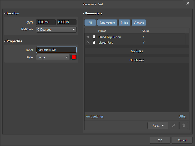
Example Altium Parameter Set

An additional custom parameter set for a ‘Listed Part’, was added to illustrate that multiple parameters could easily be added to the schematic as required.

Parameter Set in Bill of Materials
When generating the Bill of Materials (BOM) in Altium, details from the schematic parameter sets are available in the BOM Properties ‘columns’.

Altium BOM using Parameter Sets

Viewing the parameter set information in the BOM generated by Altium is possible by enabling the required parameter listed in the columns section of the BOM manager. This allows customisation of the various board fabrication or assembly houses.

Extract from Altium MiniPC Project with Parameter Sets

Pictured above is a portion of the generated BOM when the ‘Hand Population’ and ‘Listed Part’ parameter set entries were enabled.

For Altium projects that have several variants, components in schematics are likely to be controlled using the variants manager. Components are marked as fitted or not fitted. When a parameter set is used, the fitting of components with parameter sets in the BOM should be reviewed.

Thursday, 26 January 2023

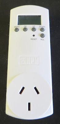
HPM D817SLIM Repair

Introduction
This short blog details the repair of an HPM main-powered digital switch timer, model D817SLIM. The fault symptoms are a blank LCD which does not restore even after the timer is plugged back into the mains.

HPM D817SLIM Mains Digital Switch Timer

Opening the Digital Timer
Disclaimer: Repair of any mains-rated electrical equipment should be conducted by qualified personnel. The information provided in this blog is for reference purposes.

The mains-powered timer (unit) had not been powered for several years and the LCD that displays the time and timer functionality was blank. Connecting the unit to the mains did not restore the operation of the LCD.

To open the unit, there are two plastic screws on the rear of the unit. The screws appear to be a Y-wing or a variant of that screw. A 2.4 mm wide flat blade was found fit the head pattern and the screws were removed. The two-piece plastic case uses internal clips so the same screwdriver can be used to unclip the case halves. There are circuit boards on either side of the plastic cases.

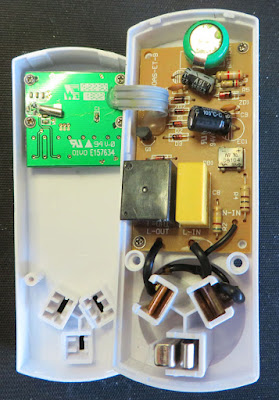
Internals of HPM D817SLIM Mains Digital Switch Timer

Dead Battery

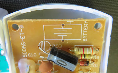
Upon opening the case, a small Ni-MH battery with corrosion or leakage was visible on the circuit board. The part was identified as a Troily 1.2 V 80 mAh Ni-MH battery.

Troily 1.2 V Ni-MH Battery

Instead of replacing the battery, it was decided to use a standard electrolytic capacitor. If this unit was to be used in an area with frequent and long interruption to mains power, a battery replacement would be advised instead of the capacitor.

To remove the circuit board with the battery, two small Philips screws were removed.

Removed Troily Battery
Removed Troily Battery from HPM Circuit Board


Battery Replacement
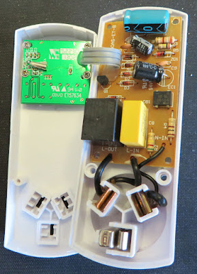
The battery was then unsoldered and replaced with a 1000 uF 25 V electrolytic capacitor. Since the operating voltage of the mains timer circuit is less than 5 V, a 6.3 V capacitor with a larger capacity could likely be used. Testing showed that with a 1000 uF electrolytic capacitor, the switch timer remained powered for approximately 6 minutes after a mains failure.

HPM D817SLIM Mains Digital Switch Timer with Capacitor

Other options to repair the unit, such as replacing the Ni-MH battery with a similar type or using a supercapacitor may be possible.

Sunday, 11 December 2022

240 V AC Mains Adaptor for Rachio 3 Smart Controller

Introduction
This microblog details the process of fitting a
240 V AC mains transformer to the Rachio 3 outdoor enclosure. The solution does not require a separate step-down transformer.

Rachio 3 Smart Controller Enclosure with 240 V AC Mains Transformer

 Details
The Rachio reticulation controller is shipped with a 110 V AC to 24 V AC transformer (adaptor). While the provided transformer alone is unsuitable in regions where the main supply grid is a different voltage, there is an alternative transformer that fits inside the Rachio weatherproof enclosure.

The 240 V AC to 24 V AC transformer is available from suppliers such as Amazon, Altronics or the BourneSuperStore.

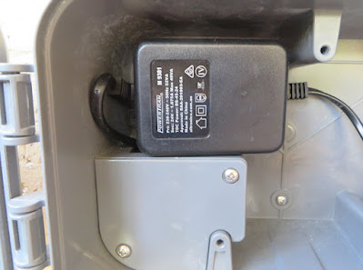
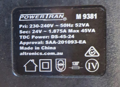
PowerTran 24 V AC Transformer Plate. Altronics M 9381

Fitting


Disclaimer: The voltages present in this post are 240V AC. Care and steps should be taken to prevent electrocution. Wiring should only be performed by experienced persons.

The previous mains socket was removed from the Rachio outdoor enclosure to fit the alternative transformer. The socket assembly is a snap design that can be removed using a screwdriver.

Mains Socket from Rachio Weatherproof Enclosure

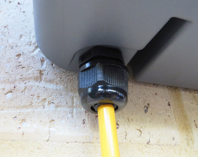
A separate double-insulated mains cable was provided to the Rachio enclosure through a 25 mm cable gland for the mains supply.

Rachio Weatherproof Enclosure with Cable Gland

The alternative transformer was supplied with a moulded mains plug. Mains termination was made by shortening the transformer cable and then connecting it to the outside mains cable. The existing section in the external enclosure was used for termination.

Mains Cable Termination in Rachio Weatherproof Enclosure

The transformer was placed in the upper left corner of the enclosure.

Installed 240 V AC to 24 V AC Mains Transformer

Following the installation of the alternative mains transformer, the process for
wiring the Rachio controller was followed.

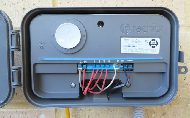
Rachio 3 Smart Controller Mounted in Weatherproof Enclosure

Sunday, 27 November 2022

Adafruit 4435 PCB Shape and Dimenstions

Introduction
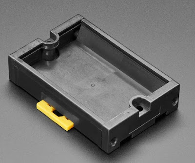
This microblog provides the dimensions and clearances required when a circuit board is used with an Adafruit DIN rail holder circuit board holder, part number 4435.

Adafruit DIN Rail Board Holder (Courtesy Adafruit)

Circuit Board and Keep Out Dimensions
The dimensions provided in the Adafruit 4435 datasheet are precise for the
circuit board shape however the information does not include any other clearances. For component placement on the circuit board, an area of 46.6 mm x 70 mm is available. The rails that hold the circuit board consume some board space. 

The purple line shown inside the object below (Keep Out Area) shows the area that can be used for components or hardware.

Adafruit (4435) Circuit Board Dimensions and Usable Board Area

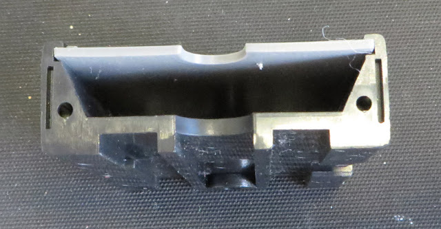
The distance between the bottom side of the example circuit board and the DIN rail holder is approximately 8 mm (assuming a 1.6 mm board). The separation between the faces is closer to 8.5 mm although factors such as thermal expansion and circuit board warping should be taken into account.

Adafruit (4435) Printed Example Circuit Board Showing Clearance to Case

Keep Out Area Validation
In each corner of a example circuit board, at the edge of the keep-out region, an extruded feature was placed.
Circuit Board Positioning Feature

A 3D model of the circuit board was printed. For validation testing, this circuit board was fit into the Adafruit DIN rail holder. Using a feature on the printed model allows easy checking of tolerances, especially between horizontal and vertical faces.
Example 3D Printed Circuit Board in Adafruit DIN Holder (4435)

 
Downloads

The files and models provided below are without the raised feature mentioned in this blog.

Circuit Board Shape and Component Keep Out for Adafruit 4435 (DWG)

 
Circuit Board Shape for Adafruit 4435 (STEP)


Saturday, 19 November 2022

EPEVER MPPT to Elfin EW11A Adaptor Circuit Board

Introduction
This blog follows on from a previous post relating to WiFi communication with an EPEVER MPPT. In this post, a DIN rail mount adaptor was created to power the Elfin EW11A (WiFi to RS485) device.

EPEVER MPPT to Elfin EW11A Adaptor

Wiring
In a previous post, the connection to an EPEVER MPPT was tested using an Elfin EW11A that was set up for station-mode WiFi operation. The test wiring described in this post was clumsy so a permanent fixture was designed.

DIN Rail Mount Solution
The connections required for the circuit board between the MPPT and EW11A were already established and tested. To power EW11A, a Texas Instruments DC-DC buck converter was selected. 

To mount the circuit board containing the aforementioned parts and rather than spinning up a 3D printed part, Adafruit’s DIN rail mount was used.

Schematic
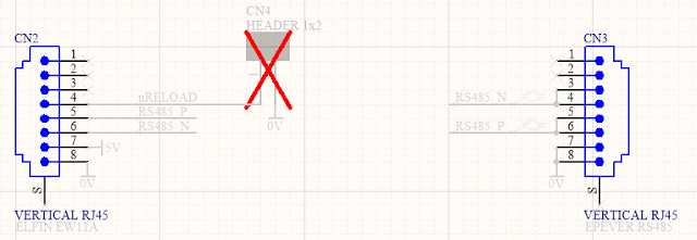
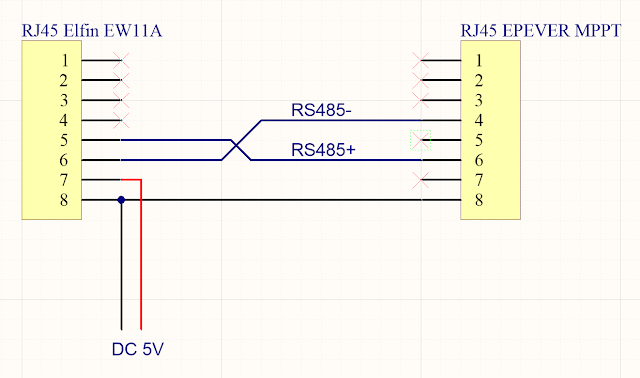
The RS485 schematic connection between the MPPT and EW11A using RJ45 connectors is shown below.

Circuit Board Connections for EPEVER MPPT to Elfin EW11A

In the power supply circuit shown below, a reverse polarity protection diode is at the front end of the design. Following the polarity diode is an optional transient diode (TVS) clamp and PI filter. Bypassing the filter is possible using the two optional bypass resistors which were added in revision 1 of the circuit board. Powering the EW11A is a DC-DC buck converter, notably the Texas Instruments LMR14203; no linear regulators here. At the time of writing the lead time of TI regulators exceeds a year so some equivalents could be the LMR16006X, LMR16006Y or MP2451DJ; these alternatives should be reviewed for compatibility.

Circuit Board Connections for Elfin EW11A Power Supply

For the sundry items on the board, a power LED was included but to conserve power this device could be unpopulated or the series current limiting resistor increased.
To reset the EW11A, a pair of circuit board pins were provided on the circuit board. Shorting the two pins provided on the circuit board will perform the reset.

Circuit Board (PCB)
The board shape was designed using the dimensions shown on the DIN holder datasheet (Adafruit website). The fitment of the circuit board in the DIN holder was accurate, although the placement of components near the edge of the circuit board was tight. A larger keep-out for the components from the edge of the circuit boards was included in the next revision of the board.

EPEVER MPPT to Elfin EW11A Circuit Rev 1 Board Top Layer

EPEVER MPPT to Elfin EW11A Circuit Board Rev 1 Bottom Layer

Testing
The populated circuit board was powered with DC 24 V and load-tested. No temperature, climate or similar tests were performed.

With no load, the DC output voltage was 5.02 V with a quiescent current of 5 mA (LED). The output voltage dropped to 4.98 V when the EW11A was powered by the regulator. Greater than DC 6 V should be provided to the DC-DC converter for stable operation.

EPEVER MPPT to Elfin EW11A Circuit Board Rev 0 Bottom Layer

A functional soak test of the circuit board over a 24-hours showed no issues. No dropped packets were detected by the virtual COM port application "HW Virtual Serial Port", version 3.1.2.

Downloads
Listed below are the MPPT to EW11A adaptor schematics, circuit board Gerber files and project Bill of Materials. The blank circuit boards can be made available at PCB Way using their Shared Projects option. The supplied schematic and Bill of Materials are for a fully populated circuit board.

Disclaimer: Please note that revision 0 of the the circuit board was tested in this post; no functional changes relating to the MPPT or EW11A connections were made in revision 1 of the circuit board.

Elfin to EPEVER Rev 1 Schematic

Elfin to EPEVER Rev 1 PCB

Elfin to EPEVER Rev 1 BOM (Full)
Elfin to EPEVER Rev 1 BOM (Full) Excel

Elfin to EPEVER Rev 1 Gerber and NC Drill

Tuesday, 8 November 2022

EPEVER MPPT to PC using RS485 or WiFi

Introduction
This blog provides two methods for connecting an EPEVER MPPT with RS485 capability to a Windows PC running Solar Station Monitor.

EPEVER Solar Station Monitor

Direct Connection
Direct connection utilises hardware consisting of an FTDI USB to RS485 adaptor, part USB-RS485-WE with an RJ45 male to screw terminal adaptor to connect to the EPEVER MPPT.

Details for the various connections using the FTDI adaptor are pictured below.

RS485 connections A, B and 0 V were used; no termination resistor was added to the circuit.

FDTI RS485 to EPEVER MPPT

Wired USB FTDI to RJ45 adaptor.

FDTI RS485 to RJ45 8-Way Screw Terminal for EPEVER MPPT

FTDI adaptor wiring from USB-RS485-WE manual.

USB-RS485-WE Connections (Courtesy FTDI)

 Pinout for RJ45 connector.

RJ45 Pinouts
RJ45 Pinouts (Courtesy Huawei)

There were no requirements to change the Windows setup for the FTDI adaptor. This device appears as a standard COM port. This COM port was then selectable in the EPEVER Solar Station Monitor application.

Wireless Connection
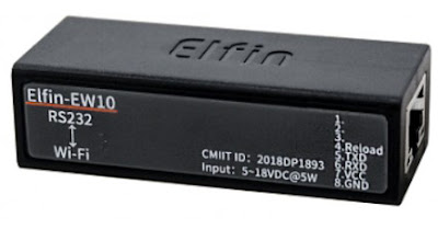
The wireless connection makes use of an Elfin EW11A. This device bridges RS485 and wireless station and or access point.

Elfin EW11A (Courtesy Hi-Flying)

Also used in the hardware solution was the optional Elfin adaptor cable. For connecting to the EPEVER MPPT, an RJ45 male to screw terminal adaptor was utilised. Since the EW11A requires DC 5 V, an further connection to a power supply is also required.


Elfin EW11A to EPEVER MPPT

Elfin EW11A to RJ45 8-Way Screw Terminal

The computer running EPEVER Solar Station Monitor required a software Ethernet to COM port bridge. The HW Virtual Serial Port application from HW-Group was used.
Side note. The EPEVER WiFi 2.4 G RJ45 A adaptor was tested separately however because WiFi Station mode was required, the EPEVER was not suitable.


Elfin EW11A Setup

This tests in this blog were geared towards verifying that wireless communications with the MPPT were practicable. The final goal was to interface the EPEVER with Home Assistant.

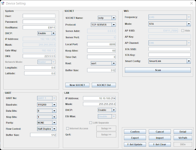
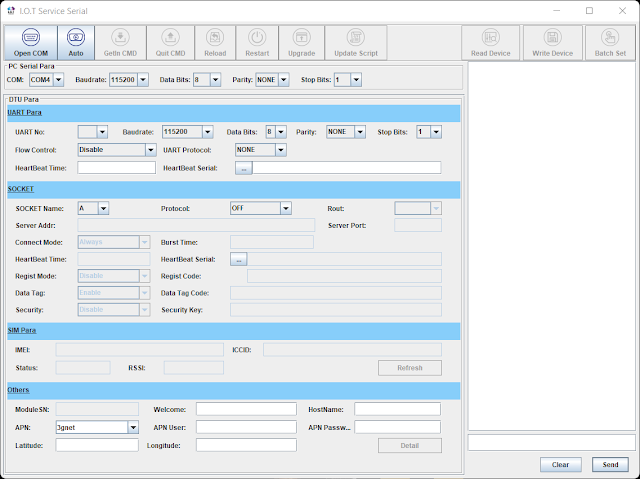
Using the I.O.T Workshop application from High-Flying, the EW11A was configured for station mode, TCP server and the port settings were configured for consistency with Home Assistant. Ethernet port number 8899 (MQTT) was used. The Comment and Application Guide from Eniris was used as the primary reference document.

Removed from the screen capture below are the login details (admin and password), wireless station ID and associated password.

EW11A Device Setup for EPEVER MPPT Using I.O.T Workshop

No UART protocol was selected. Telnet was disabled and web interface was kept enabled.

EW11A Device Detail for EPEVER MPPT Using I.O.T Workshop

The UART settings 115200, 8, N, 1 were left as default.

EW11A Serial Setup for EPEVER MPPT Using I.O.T Workshop

Virtual Serial Port
For this blog the
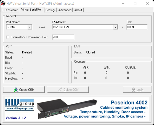
HW Virtual Serial Port application from HW-Group was used. The default configuration of the application required changes. For example, if the option Network Virtual Terminal (NVT) was enabled, communications with the EPEVER MPPT were sporadic or only specific values were received correctly. Other tools offering an Ethernet to COM virtual com port may offer similar configuration options which should be validated.

HW Virtual Serial Port Settings for EPEVER MPPT  and Elfin EW11A
HW Virtual Serial Port Settings for EPEVER MPPT and Elfin EW11A

Shown on the Virtual Serial Port page is the IP and port for the Elfin EW11A.

HW Virtual Serial Port Page for EPEVER MPPT with Elfin EW11A

With the Elfin EW11A configured and powered, clicking Create COM in the virtual serial port application established the Ethernet link. Shortly after COM4 appeared in Windows Device Manager.

Serial Port Created Using HW Virtual Serial Port

With a connection established to the EW11A and the EPEVER MPPT, the EPEVER application could communicate with the MPPT. This was indicated by the change in counter values (Rx and Tx).

HW Virtual Serial Port Connected to EPEVER MPPT with Elfin EW11A

Solar Station Monitor
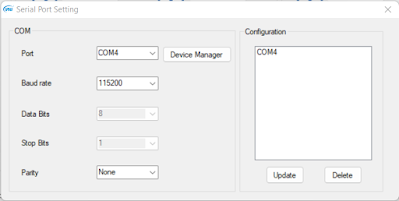
No changes were made to the setup of the EPEVER Solar Station Monitor application other than configuring the required COM port to communicate with the Virtual COM port.
The default port settings were used.

EPEVER COM Port Settings
 

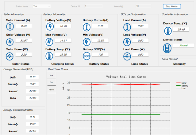
After clicking Start Monitor in the application, data was exchanged within a few seconds.

The capture below was taken after sunset with the MPPT load active.

EPEVER Solar Station Monitor (Load Active)

The capture below was taken during sunlight hours.

EPEVER Solar Station Monitor (During Daylight)


For the capture below, the EPVER monitoring tool was restarted to capture the transition between load OFF and ON.

EPEVER Solar Station Monitor Graphed Data Showing Load ON

EPEVER Solar Station Monitor Graphed Data Showing Load OFF

Final Thoughts
This post offered two methods for connecting an EPEVER MPPT with a Windows PC running Solar Station Monitor application. The WiFi connection and subsequent testing using the Elfin EW11A served as preliminary work to develop a dedicated circuit board to bridge the EW11A with the EPEVER MPPT.